RTL Systolic Array
A parameterizable SystemVerilog systolic array for matrix multiplication, streamed over AXI4-Stream.
A parameterizable hardware implementation of a 2D Systolic Array in SystemVerilog, designed primarily for accelerating multiplication of N x N matrices of signed integers. This project features a high-performance AXI4-Stream instrumentation bridge to stream input matrices and extract the computed results efficiently. This specific protocol was chosen because it is non-memory-mapped, which forgoes the complexity needed for an AXI4 or AXI4-Lite bus implementation while allowing matrix data to be continuously transmitted (or “streamed”) while the instrumentation FSM is in the RECV_A and RECV_B states.
Overview
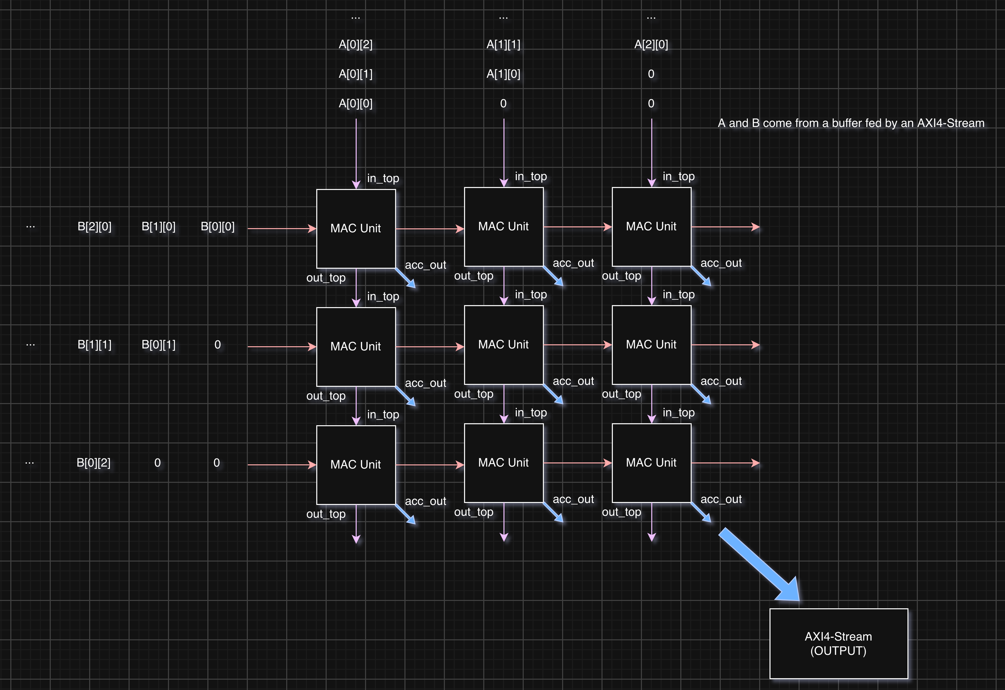
A systolic array computes matrix multiplication (\(C = A \times B\)) by pipelining the data flow through a mesh of identically structured Processing Elements (PEs). Essentially, this turns matrix multiplication from \(O(n^3)\) to \(O(n)\) by rolling out two dimensions into hardware. In this particular output-stationary design, matrix \(A\) rows stream horizontally, matrix \(B\) columns stream vertically, and partial sums accumulate within each PE or are passed along.
Key Components
systolic_array.sv: The top-level array module. It handles data buffering and the necessary time-skewing logic so that matrix elements arrive at the correct Processing Element at the right clock cycle. Features parameterized array dimension (N) and precision (DATA_WIDTH).multiply_accumulate_unit.sv: The core Processing Element (PE). It performs a synchronous multiply-accumulate operation (acc_out <= acc_in + in_top * in_side) and pass-through forwarding of thetopandsidedata to adjacent PEs.instrumentation.sv: The top-level state machine. It implements an AXI4-Stream interface (Master and Slave) wrapping the systolic array. This state machine manages the streaming of Matrix A and Matrix B into internal buffers, handles the ready/valid handshakes, drives the array for computation, and streams the resulting Matrix C out.uart_rx.sv(unused): A 16x oversampled UART receiver state machine with a default BAUD rate of 115.2 kbps. This module was originally intended to serve as the communication bridge, allowing a host PC to stream matrices to the FPGA/accelerator. However, I later switched to an AXI4-Stream interface to improve performance.
These components can be found in the rtl directory.
Architecture
Top-Level Block Diagram
To come
Controller FSM
To come
Verification & Simulation
File Structure and Build Instructions
The project uses Verilator for simulation and linting.
Testbenches are located in the tb/ directory:
tb_systolic_array.sv: Defines a SystemVeriloginterface(sys_if) and a basic object-oriented testbench scaffold (e.g., generator, mailbox) to drive the matrix inputs. The generator produces basic test matrices consisting of a simple pattern and a identity matrix, the driver feeds these matrices into the systolic array interface, and the scoreboard verifies that multiplying by the identity leaves the pattern matrix unchanged.golden-model.py: Not a testbench, but rather a script to generate random input matrices and compute the “golden model” expected output vianumpy. The script is seeded so the random matrix generation remains deterministic, and the three matrices are serialized into hex files in row-major order.tb_instrumentation.sv: The generator loads the random matrices from the python script with$readmemh, the driver controls the AXI handshakes, and the scoreboard verifies the output against the golden model expected output (also loaded withreadmemh).tb_uart_rx.sv: Testbench for validating the UART receiver logic.
The Verilator build configuration is specified in verilator.f, and past runs are available in the waveforms/ directory for debugging.
To run the instrumentation testbench:
verilator -f verilator.f
./obj_dir/Vtb_instrumentation
To generate random matrices and a golden model result using Python, install numpy and run the golden-model.py script.
Everything has been tested on macOS, but it should be cross-platform as it relies solely on Python, numpy, and Verilator.
Waveforms
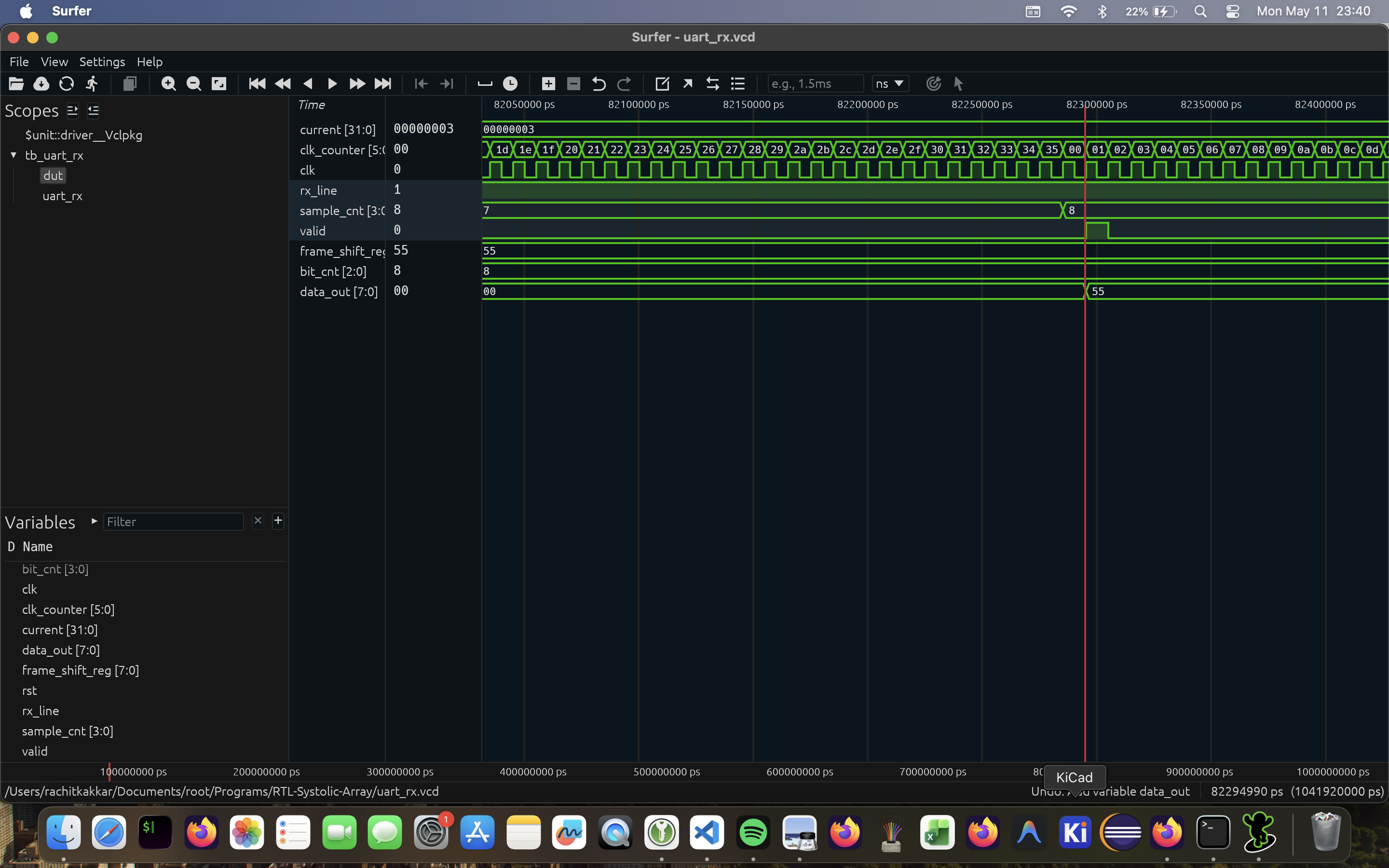
tb_uart_rx.sv (unused)
Scoreboard Console Result
tb_instrumentation.sv
[SCOREBOARD] Loaded gold_result.hex
[GEN] Loaded matrix_a.hex and matrix_b.hex
[DRIVER] All data sent.
[SCOREBOARD][PASS] C[0][0] = -10794
[SCOREBOARD][PASS] C[0][1] = -3796
[SCOREBOARD][PASS] C[0][2] = 8814
[SCOREBOARD][PASS] C[0][3] = 1490
[SCOREBOARD][PASS] C[0][4] = -15529
[SCOREBOARD][PASS] C[0][5] = -5646
[SCOREBOARD][PASS] C[0][6] = 25923
[SCOREBOARD][PASS] C[0][7] = -4795
...
[SCOREBOARD][PASS] C[7][7] = 7693
[SCOREBOARD] --- Summary: 64 PASS, 0 FAIL ---
[TB] Simulation completed.
- tb/tb_instrumentation.sv:267: Verilog $finish
- S i m u l a t i o n   R e p o r t: Verilator 5.044 2026-01-01
- Verilator: $finish at 50us; walltime 0.002 s; speed 40.371 ms/s
- Verilator: cpu 0.001 s on 1 threads; alloced 2 MB
Parameterization
The core array and AXI bridge can be configured at instantiation:
instrumentation #(
  .N(8),               // Dimension of the NxN array
  .DATA_WIDTH(8)       // Bit-width for matrix inputs
) inst_module ( ... );
Note: The accumulator width automatically scales to 2 * DATA_WIDTH to prevent overflow during standard integer operations, and the AXI data widths are derived directly from the array dimensions.
To-do
Finish README, actually try synthesizing.